SlideShare a Scribd company logo
1 of 4
Some Solved Questions
Q1. Draw the pu impedance diagram for the power system shown in the figure . Neglect
resistance , and use a base of 100 MV A , 230 kV in 50 Ω line. The ratings of the
generator , motor and transformers are : Generator 40 MV A, 25 kV, X” = 20%
                      Motor 50 MV A, 11 kV, X” = 30%
                      Y-Y transformer, 40 MV A, 33 Y-220 Y kV, X = 15%
                      Y-Δ transformer, 30 MV A, 11 Δ-220 Y kV, X = 15%


 Solution: The rectangular blocks are circuit breakers and it is connected at the beginning
and end of each m/c or transformer or transmission line to protect it from high current
due to faults. We don’t have to bother about it. Just neglect it – do not get confused.
Step 1: Identifying the circuits: Let us name it as ckt.1 , ckt(trans line) and ckt 2.
Step 2 : Marking the new bases for each of the 3 ckts.
Ckt(trans line): we should start from this as this is what is given in the question.
And it is 100MVA and 230KV.
Ckt 1: we know the base voltage on the right side of transformer but not left side. The
base on left side (ckt 1) depends on the transformation ratio of Y- Y transformer which is
coming into picture when we are going from transmission line to generator ckt.
Hence VB(ckt 1) / VB(ckt trans line) = 33/220 (since the higher voltage side is always connected
towards the transmission line side)
VB(ckt 1) = 34.5KV
Ckt 2 : Similarly
VB(ckt trans line) / VB(ckt 2) = 220/11
VB(ckt 2) = 11.5KV
Step 3 : Calculating the new reactances
Generator: Xg = 0.2 x (100/40) x (25/34.5)2 = 0.2625pu
Transformer (Y-Y) on the primary side = 0.15 x (100/40) x (33/34.5)2 = 0.343pu
                      on the secondary side = 0.15 x (100/40) x (220/230)2 = 0.343pu
And we notice that whether we do calculations on primary or secondary side, the pu
value does not change for a transformer.
Transformer (Y- Δ) on the primary side = 0.15 x (100/30) x (220/230)2 = 0.457pu
                      on the secondary side = 0.15 x (100/30) x (11/11.5)2 = 0.457pu
Motor: 0.3 x (100/50) x (11/11.5)2 = 0.55pu
Transmission line: Actual/ base impedance(since the actual value is given, we can
directly devide by the base value and get the pu value)
Base impedance in the transmission line circuit = 2302/ 100 = 529 ohms
Hence X (line) = 50/529 = 0.0945pu
Q2.The Figure shows the schematic diagram of a radial transmission system. The ratings
and reactances of the various components are shown therein. A load of 60 MW at 0.9
power factor lagging is tapped from the 66 KV substation which is to be maintained at 60
kV . Calculate the terminal voltage of the synchronous machine . represent the
transmission line and the transformers by series reactances only.


 60 MW and not 60MV
Solution: Let 100 MVA and 11KV be the base in Generator circuit.
Accordingly the base in transmission line will be 100 MVA, 220 KV.
And in the load circuit, it is 100 MVA and 66KV.
Xt1 = j0.1
Xt2 = j0.08
X line = 150/(2202/100) = j0.31
Iload = 60,000/(sqrt 3 x 60x 0.9) = 641.5A
Base current = 100,000/ (sqrt 3 x 66) = 874.77A
Iload (pu) = 641.5/874.77 = 0.733(-25.84 )A
                                        0


V2(pu) = 60/66 = 0.91(0 )
                        0
V1 = V2 + Iload(equivalent Reactance)
   = 0.91(0 ) + 0.733(-25.84 ) x (j0.1 + j0.31 + j0.08)
            0                0


   = 1.11(16.85 )   0


Actual V1 = 1.11 x 11 = 12.2 KV


Q3..A synchronous generator is rated 60 MVA , 11 kV. It has resistance R = 0.1 pu and
                                                                             a

X = 1.65 pu. It is feeding into an infinite bus bar at 11 kV delivering a current 3.15 kA at
 d


0.9 pf lagging.
(a) Determine E and angle δ.
                f


(b) Draw a phasor diagram for this operation.
(c) Bus bar voltage falls to 10 kV while the mechanical power input generator and its
excitation remains unchanged. What is the value and pf of the current delivered to the
bus. In this case assume the generator resistance to be negligible.

Solution:
Choose a base of 60MVA, 11kV(as the base MVA to be chosen is not given, we have the
liberty to choose the base same as the rating of the m/c.).
The bus bar voltage is to be maintained at 11KV.
When converted to p.u., it is 11/11(Actual / base) = 1.0(0 )pu
                                                          0


Base current = 60/{sqrt(3)x 11} = 3.15 KA
Actual current = 3.15KA
Hence pu Ia = 1(-cos-1 0.9) = 1(-25.84 )pu
                                       0


    (a) Ef = Vt + Ia(Ra + jIaXa) = 1.81+j1.438 = 2.312(38.47 )    0


        Hence Actual Ef = 11x2.312 = 25.43 and δ = 38.47 leading
                                                              0


     (b)


    (c) Vt = 10/11 = 0.91pu
        Mechanical power input is the input to prime mover(steam) which changes the
active power. Hence P = same as above = Vt x Ia x pf = 1 x 1 x 0.9 = 0.9pu
And P = |Vt| |Ef| sin δ/ Xa (Ef or Excitation is also not changing)
Which gives us δ = 40   0


Hence Ia = (Ef – Vt )/jXa = 1.0436(-30.35)pu
Therefore actual current = 1.0436x3.15 = 3.28 KA and pf = cos30.35 = 0.863 lagging

Q4.Three impedances of 5-j10, 6+j5 and 3+ j15 ohms are connected in star to A, B and C
lines of a 3300 V, 3 phase, 3 wire supply. The phase sequence is ABC. Calculate the line
current Ia.
Solution: this is a case of unbalanced 3 phase star connected load supplied from a
balanced 3 phase supply.
There is 3 wire and hence the phase voltages cannot be taken as balanced(since there is
no neutral connection between supply and load).
Vab = 3300(0 )
             0


Vbc = 3300(-120 )0


Let Va, Vb and Vc be the phase voltages.
Van = (5 – j10)Ia = (5-j10)(Ia1+Ia2+Ia0) = (5-j10)(Ia1+Ia2)                         (1)
Since Ia + Ib +Ic = In = 3Ia0 = 0 , hence Ia0 = 0(there is no neutral wire and hence zero
sequence currents cannot can flow.)
Vbn = (6+j5)Ib = (6+j5)(Ib1+Ib2) = (6+j5)(a2Ia1 + aIa2)                             (2)
                                                           2
Vcn = (3+j15)Ic = (3+j15)(Ic1+Ic2) == (3+j15)(aIa1 + a Ia2)                         (3)
    (1) – (2) gives us
    Van –Vbn = Vab = 3300(0) = (3.67 – j2.3)Ia1 + (12.33 – j12.7)Ia2                (4)
    (2) – (3) gives us
    Vbn – Vcn = Vbc = 3300(-120 ) = (15.8 – j2.8)Ia1 – (18.84 – j12.8)Ia2
                                    0
                                                                                    (5)
Solving (4) and (5) for Ia1 and Ia2,
Ia1 = 134-j65
Ia2 = 95 +j141
Hence Ia = Ia1+ Ia2 = 241(-18.4 ) A
                                0

More Related Content

What's hot (20)

Unit4questions
Unit4questionsUnit4questions
Unit4questions
 
Questions unit4
Questions unit4Questions unit4
Questions unit4
 
Solutions -unit4
Solutions  -unit4Solutions  -unit4
Solutions -unit4
 
Questions unit3
Questions unit3Questions unit3
Questions unit3
 
Unit v
Unit vUnit v
Unit v
 
Unit 3 Part 1
Unit 3 Part 1Unit 3 Part 1
Unit 3 Part 1
 
Unit 2 Questions_Nagrath kothari
Unit 2 Questions_Nagrath kothariUnit 2 Questions_Nagrath kothari
Unit 2 Questions_Nagrath kothari
 
Chapter1 Questions
Chapter1 QuestionsChapter1 Questions
Chapter1 Questions
 
electrical objective
electrical objectiveelectrical objective
electrical objective
 
Eet3082 binod kumar sahu lecturer_23
Eet3082 binod kumar sahu lecturer_23Eet3082 binod kumar sahu lecturer_23
Eet3082 binod kumar sahu lecturer_23
 
Electrical machines solved objective
Electrical machines solved objectiveElectrical machines solved objective
Electrical machines solved objective
 
EEP303: Exp5
EEP303: Exp5EEP303: Exp5
EEP303: Exp5
 
Lecture no 4 power system analysis elc353 et313
Lecture no 4 power system analysis elc353 et313Lecture no 4 power system analysis elc353 et313
Lecture no 4 power system analysis elc353 et313
 
Electrical machines-lab-i-ee0209
Electrical machines-lab-i-ee0209Electrical machines-lab-i-ee0209
Electrical machines-lab-i-ee0209
 
Emec 1 question
Emec 1 questionEmec 1 question
Emec 1 question
 
EEP301: Transducer and instrumentation
EEP301: Transducer and instrumentationEEP301: Transducer and instrumentation
EEP301: Transducer and instrumentation
 
Lecture 9
Lecture 9Lecture 9
Lecture 9
 
EEP303: Cycle ii exp 2
EEP303: Cycle ii   exp 2EEP303: Cycle ii   exp 2
EEP303: Cycle ii exp 2
 
Ch11 polyphase
Ch11 polyphaseCh11 polyphase
Ch11 polyphase
 
Fundamental Power System
Fundamental Power SystemFundamental Power System
Fundamental Power System
 

Similar to Unit1 and 2 sample solutions

Three phase balanced load circuits and synchronous generators
Three phase balanced load circuits and synchronous generatorsThree phase balanced load circuits and synchronous generators
Three phase balanced load circuits and synchronous generatorsIsham Rashik
 
Electronics and communication engineering_Lect14.ppt
Electronics and communication engineering_Lect14.pptElectronics and communication engineering_Lect14.ppt
Electronics and communication engineering_Lect14.pptmuhammadzaid733820
 
UNIT-III complex reactive three phase.ppt
UNIT-III complex reactive three phase.pptUNIT-III complex reactive three phase.ppt
UNIT-III complex reactive three phase.pptAbinaya Saraswathy T
 
Eet3082 binod kumar sahu lecturer_14
Eet3082 binod kumar sahu lecturer_14Eet3082 binod kumar sahu lecturer_14
Eet3082 binod kumar sahu lecturer_14BinodKumarSahu5
 
Eet3082 binod kumar sahu lecturer_14
Eet3082 binod kumar sahu lecturer_14Eet3082 binod kumar sahu lecturer_14
Eet3082 binod kumar sahu lecturer_14BinodKumarSahu5
 
Emec 1 bank nee 301
Emec 1 bank nee 301Emec 1 bank nee 301
Emec 1 bank nee 301Ravi Anand
 
Solved problems to_chapter_09
Solved problems to_chapter_09Solved problems to_chapter_09
Solved problems to_chapter_09Shah Zaib
 
Stability with analysis and psa and load flow.ppt
Stability with analysis and psa and load flow.pptStability with analysis and psa and load flow.ppt
Stability with analysis and psa and load flow.pptZahid Yousaf
 
Multi phase Star Rectifier
Multi phase Star Rectifier Multi phase Star Rectifier
Multi phase Star Rectifier ZunAib Ali
 
Power supply designed by amani james
Power supply  designed by amani  jamesPower supply  designed by amani  james
Power supply designed by amani jamesAmani James
 
Power system safety and protection
Power system safety and protectionPower system safety and protection
Power system safety and protectionHakim Futra
 

Similar to Unit1 and 2 sample solutions (20)

Three phase balanced load circuits and synchronous generators
Three phase balanced load circuits and synchronous generatorsThree phase balanced load circuits and synchronous generators
Three phase balanced load circuits and synchronous generators
 
ECE4762011_Lect14.ppt
ECE4762011_Lect14.pptECE4762011_Lect14.ppt
ECE4762011_Lect14.ppt
 
powerflowproblem.ppt
powerflowproblem.pptpowerflowproblem.ppt
powerflowproblem.ppt
 
Electronics and communication engineering_Lect14.ppt
Electronics and communication engineering_Lect14.pptElectronics and communication engineering_Lect14.ppt
Electronics and communication engineering_Lect14.ppt
 
ECE4762011_Lect14.ppt
ECE4762011_Lect14.pptECE4762011_Lect14.ppt
ECE4762011_Lect14.ppt
 
Report_AKbar_PDF
Report_AKbar_PDFReport_AKbar_PDF
Report_AKbar_PDF
 
ECNG 6503 #4
ECNG 6503 #4ECNG 6503 #4
ECNG 6503 #4
 
UNIT-III complex reactive three phase.ppt
UNIT-III complex reactive three phase.pptUNIT-III complex reactive three phase.ppt
UNIT-III complex reactive three phase.ppt
 
Lecture 2
Lecture 2Lecture 2
Lecture 2
 
Lecture 12
Lecture 12Lecture 12
Lecture 12
 
Eet3082 binod kumar sahu lecturer_14
Eet3082 binod kumar sahu lecturer_14Eet3082 binod kumar sahu lecturer_14
Eet3082 binod kumar sahu lecturer_14
 
Eet3082 binod kumar sahu lecturer_14
Eet3082 binod kumar sahu lecturer_14Eet3082 binod kumar sahu lecturer_14
Eet3082 binod kumar sahu lecturer_14
 
Lecture 13
Lecture 13Lecture 13
Lecture 13
 
Emec 1 bank nee 301
Emec 1 bank nee 301Emec 1 bank nee 301
Emec 1 bank nee 301
 
Solved problems to_chapter_09
Solved problems to_chapter_09Solved problems to_chapter_09
Solved problems to_chapter_09
 
Stability with analysis and psa and load flow.ppt
Stability with analysis and psa and load flow.pptStability with analysis and psa and load flow.ppt
Stability with analysis and psa and load flow.ppt
 
Multi phase Star Rectifier
Multi phase Star Rectifier Multi phase Star Rectifier
Multi phase Star Rectifier
 
Power supply designed by amani james
Power supply  designed by amani  jamesPower supply  designed by amani  james
Power supply designed by amani james
 
Assignmentl3 solutions
Assignmentl3 solutionsAssignmentl3 solutions
Assignmentl3 solutions
 
Power system safety and protection
Power system safety and protectionPower system safety and protection
Power system safety and protection
 

More from Abha Tripathi

Power system Stability, Equal area criteria
Power system Stability, Equal area criteriaPower system Stability, Equal area criteria
Power system Stability, Equal area criteriaAbha Tripathi
 
Non Conventional (Renewable) Energy Sources 01
Non Conventional (Renewable) Energy Sources 01Non Conventional (Renewable) Energy Sources 01
Non Conventional (Renewable) Energy Sources 01Abha Tripathi
 
Conventional sources of energy (power generation) 01
Conventional sources of energy (power generation) 01Conventional sources of energy (power generation) 01
Conventional sources of energy (power generation) 01Abha Tripathi
 
Symmetrical components
Symmetrical componentsSymmetrical components
Symmetrical componentsAbha Tripathi
 
Representation of power system components
Representation of power system componentsRepresentation of power system components
Representation of power system componentsAbha Tripathi
 
Gas and diesel Plant
Gas and diesel PlantGas and diesel Plant
Gas and diesel PlantAbha Tripathi
 
NPP, Nuclear Power Plant,
NPP, Nuclear Power Plant, NPP, Nuclear Power Plant,
NPP, Nuclear Power Plant, Abha Tripathi
 
Grading The Insulator Problem
Grading The Insulator ProblemGrading The Insulator Problem
Grading The Insulator ProblemAbha Tripathi
 

More from Abha Tripathi (16)

Power system Stability, Equal area criteria
Power system Stability, Equal area criteriaPower system Stability, Equal area criteria
Power system Stability, Equal area criteria
 
Non Conventional (Renewable) Energy Sources 01
Non Conventional (Renewable) Energy Sources 01Non Conventional (Renewable) Energy Sources 01
Non Conventional (Renewable) Energy Sources 01
 
Conventional sources of energy (power generation) 01
Conventional sources of energy (power generation) 01Conventional sources of energy (power generation) 01
Conventional sources of energy (power generation) 01
 
Symmetrical components
Symmetrical componentsSymmetrical components
Symmetrical components
 
Representation of power system components
Representation of power system componentsRepresentation of power system components
Representation of power system components
 
Questions unit2 ch3
Questions unit2 ch3Questions unit2 ch3
Questions unit2 ch3
 
Unit1questions
Unit1questionsUnit1questions
Unit1questions
 
Renewable Sor
Renewable SorRenewable Sor
Renewable Sor
 
Gas and diesel Plant
Gas and diesel PlantGas and diesel Plant
Gas and diesel Plant
 
NPP, Nuclear Power Plant,
NPP, Nuclear Power Plant, NPP, Nuclear Power Plant,
NPP, Nuclear Power Plant,
 
Hydro E
Hydro EHydro E
Hydro E
 
Thermal power plant
Thermal power plantThermal power plant
Thermal power plant
 
Unit 3 Part 1
Unit 3 Part 1Unit 3 Part 1
Unit 3 Part 1
 
Grading The Insulator Problem
Grading The Insulator ProblemGrading The Insulator Problem
Grading The Insulator Problem
 
Dc Distribution
Dc DistributionDc Distribution
Dc Distribution
 
Dc Distributed Load
Dc Distributed LoadDc Distributed Load
Dc Distributed Load
 

Unit1 and 2 sample solutions

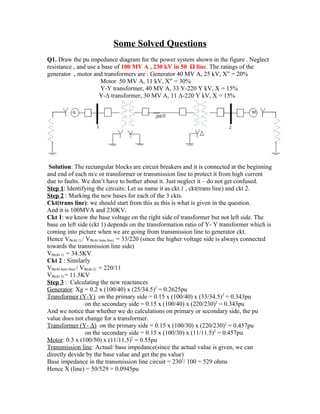
  • 1. Some Solved Questions Q1. Draw the pu impedance diagram for the power system shown in the figure . Neglect resistance , and use a base of 100 MV A , 230 kV in 50 Ω line. The ratings of the generator , motor and transformers are : Generator 40 MV A, 25 kV, X” = 20% Motor 50 MV A, 11 kV, X” = 30% Y-Y transformer, 40 MV A, 33 Y-220 Y kV, X = 15% Y-Δ transformer, 30 MV A, 11 Δ-220 Y kV, X = 15% Solution: The rectangular blocks are circuit breakers and it is connected at the beginning and end of each m/c or transformer or transmission line to protect it from high current due to faults. We don’t have to bother about it. Just neglect it – do not get confused. Step 1: Identifying the circuits: Let us name it as ckt.1 , ckt(trans line) and ckt 2. Step 2 : Marking the new bases for each of the 3 ckts. Ckt(trans line): we should start from this as this is what is given in the question. And it is 100MVA and 230KV. Ckt 1: we know the base voltage on the right side of transformer but not left side. The base on left side (ckt 1) depends on the transformation ratio of Y- Y transformer which is coming into picture when we are going from transmission line to generator ckt. Hence VB(ckt 1) / VB(ckt trans line) = 33/220 (since the higher voltage side is always connected towards the transmission line side) VB(ckt 1) = 34.5KV Ckt 2 : Similarly VB(ckt trans line) / VB(ckt 2) = 220/11 VB(ckt 2) = 11.5KV Step 3 : Calculating the new reactances Generator: Xg = 0.2 x (100/40) x (25/34.5)2 = 0.2625pu Transformer (Y-Y) on the primary side = 0.15 x (100/40) x (33/34.5)2 = 0.343pu on the secondary side = 0.15 x (100/40) x (220/230)2 = 0.343pu And we notice that whether we do calculations on primary or secondary side, the pu value does not change for a transformer. Transformer (Y- Δ) on the primary side = 0.15 x (100/30) x (220/230)2 = 0.457pu on the secondary side = 0.15 x (100/30) x (11/11.5)2 = 0.457pu Motor: 0.3 x (100/50) x (11/11.5)2 = 0.55pu Transmission line: Actual/ base impedance(since the actual value is given, we can directly devide by the base value and get the pu value) Base impedance in the transmission line circuit = 2302/ 100 = 529 ohms Hence X (line) = 50/529 = 0.0945pu
  • 2. Q2.The Figure shows the schematic diagram of a radial transmission system. The ratings and reactances of the various components are shown therein. A load of 60 MW at 0.9 power factor lagging is tapped from the 66 KV substation which is to be maintained at 60 kV . Calculate the terminal voltage of the synchronous machine . represent the transmission line and the transformers by series reactances only. 60 MW and not 60MV Solution: Let 100 MVA and 11KV be the base in Generator circuit. Accordingly the base in transmission line will be 100 MVA, 220 KV. And in the load circuit, it is 100 MVA and 66KV. Xt1 = j0.1 Xt2 = j0.08 X line = 150/(2202/100) = j0.31 Iload = 60,000/(sqrt 3 x 60x 0.9) = 641.5A Base current = 100,000/ (sqrt 3 x 66) = 874.77A Iload (pu) = 641.5/874.77 = 0.733(-25.84 )A 0 V2(pu) = 60/66 = 0.91(0 ) 0
  • 3. V1 = V2 + Iload(equivalent Reactance) = 0.91(0 ) + 0.733(-25.84 ) x (j0.1 + j0.31 + j0.08) 0 0 = 1.11(16.85 ) 0 Actual V1 = 1.11 x 11 = 12.2 KV Q3..A synchronous generator is rated 60 MVA , 11 kV. It has resistance R = 0.1 pu and a X = 1.65 pu. It is feeding into an infinite bus bar at 11 kV delivering a current 3.15 kA at d 0.9 pf lagging. (a) Determine E and angle δ. f (b) Draw a phasor diagram for this operation. (c) Bus bar voltage falls to 10 kV while the mechanical power input generator and its excitation remains unchanged. What is the value and pf of the current delivered to the bus. In this case assume the generator resistance to be negligible. Solution: Choose a base of 60MVA, 11kV(as the base MVA to be chosen is not given, we have the liberty to choose the base same as the rating of the m/c.). The bus bar voltage is to be maintained at 11KV. When converted to p.u., it is 11/11(Actual / base) = 1.0(0 )pu 0 Base current = 60/{sqrt(3)x 11} = 3.15 KA Actual current = 3.15KA Hence pu Ia = 1(-cos-1 0.9) = 1(-25.84 )pu 0 (a) Ef = Vt + Ia(Ra + jIaXa) = 1.81+j1.438 = 2.312(38.47 ) 0 Hence Actual Ef = 11x2.312 = 25.43 and δ = 38.47 leading 0 (b) (c) Vt = 10/11 = 0.91pu Mechanical power input is the input to prime mover(steam) which changes the active power. Hence P = same as above = Vt x Ia x pf = 1 x 1 x 0.9 = 0.9pu And P = |Vt| |Ef| sin δ/ Xa (Ef or Excitation is also not changing) Which gives us δ = 40 0 Hence Ia = (Ef – Vt )/jXa = 1.0436(-30.35)pu
  • 4. Therefore actual current = 1.0436x3.15 = 3.28 KA and pf = cos30.35 = 0.863 lagging Q4.Three impedances of 5-j10, 6+j5 and 3+ j15 ohms are connected in star to A, B and C lines of a 3300 V, 3 phase, 3 wire supply. The phase sequence is ABC. Calculate the line current Ia. Solution: this is a case of unbalanced 3 phase star connected load supplied from a balanced 3 phase supply. There is 3 wire and hence the phase voltages cannot be taken as balanced(since there is no neutral connection between supply and load). Vab = 3300(0 ) 0 Vbc = 3300(-120 )0 Let Va, Vb and Vc be the phase voltages. Van = (5 – j10)Ia = (5-j10)(Ia1+Ia2+Ia0) = (5-j10)(Ia1+Ia2) (1) Since Ia + Ib +Ic = In = 3Ia0 = 0 , hence Ia0 = 0(there is no neutral wire and hence zero sequence currents cannot can flow.) Vbn = (6+j5)Ib = (6+j5)(Ib1+Ib2) = (6+j5)(a2Ia1 + aIa2) (2) 2 Vcn = (3+j15)Ic = (3+j15)(Ic1+Ic2) == (3+j15)(aIa1 + a Ia2) (3) (1) – (2) gives us Van –Vbn = Vab = 3300(0) = (3.67 – j2.3)Ia1 + (12.33 – j12.7)Ia2 (4) (2) – (3) gives us Vbn – Vcn = Vbc = 3300(-120 ) = (15.8 – j2.8)Ia1 – (18.84 – j12.8)Ia2 0 (5) Solving (4) and (5) for Ia1 and Ia2, Ia1 = 134-j65 Ia2 = 95 +j141 Hence Ia = Ia1+ Ia2 = 241(-18.4 ) A 0